The types of trusses they can vary depending on the balance, conformation and origin or designer. Known as flat or spatial lattices or as lattices and reinforcements, in engineering terms they are rigid structures reinforced by straight rods at their ends that present a triangular shape..
This type of configuration has the property of supporting loads in its plane, especially those that act on the joints or nodes. Consequently, its application in construction is of great importance, because it is an articulated and non-deformable system that does not cut or flex. This implies that its elements participate actively in terms of compression and traction..
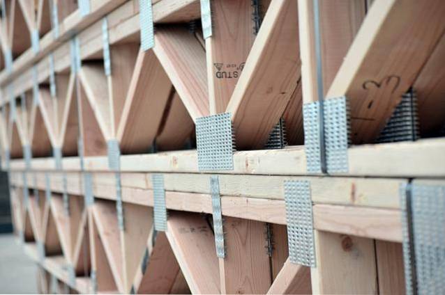
Unlike the square, this triangular formation is not unstable, so it can be applied in small or large works. The trusses can be composed of different materials, the most used being wooden, metallic and reinforced concrete..
Depending on the use that you want to give this kind of framework, they are generally applied in the construction of warehouse ceilings, industrial warehouses, aircraft hangars, churches, stadiums, bridges or beam systems..
A truss can be totally isostatic or statically determined in relation to the mechanical balance applied to the external shape of the structure. The same happens with the internal elements, which are evaluated in their reactions and efforts to know their stability. The categories resulting from this evaluation have been established as follows:
This concept refers to a class of structure that can be analyzed using the principles and formulas that reveal static values. As referred to, its nature is statically determined, so the removal of some of the components that bind the frame as such, would cause a catastrophic failure of the entire system..
The essence of this type of configuration is its equilibrium state, which means that the bending moment has a value equal to 0 in each of the bars that make up the system..
Despite this condition, the truss may present conditions of instability due to the type of design with fixed nodes that can resemble an isostatic structure..
This type of trusses has a flat structure that is composed of articulated knots and that have various shapes:
This truss is a statically defined conformation, so the number of rods and the number of pin joints must meet the appropriate formula. It presents the known shape of a triangle and its calculation is based on graphical statics and the balance of the nodes.
Like the previous one, they present a structure with static determination that can be designed from 1 or 2 simple trusses. In this case, both structures are joined by an additional bar at a common point so that they remain fixed. They can also include 3 additional poles or an internal frame that meets balance criteria.
Since they belong to the category of hyperstatic, their difference lies in the fact that it does not exclude the previous models and includes the rest of the geometries. Although it is composed of fixed joints, its calculation can be done using the Heneberg method or the matrix method of stiffness. The first is more approximate, while the second is much more precise.
On the other hand, some commonly used trusses are named after their creators, who studied them or the city where they were first applied. Among them, the following stand out:
This variant appeared in 1835 and is related to Stephen H. Long. It is a design in which the top and bottom horizontal chords are joined by vertical studs. The whole set is braced by double diagonals and resembles X's enclosed by squares..
Although it had been used before, this structure was patented in 1840 by William Howe. Also known as Belgian, it uses vertical studs between the top and bottom chord and is widely applied to wood. In this design it is made up of diagonal bars that receive compression and other vertical ones that support traction..
Created by Caleb and Thomas Pratt in 1844, it is a variation of the previous model but with a more resistant material: steel. It differs from Howe's truss in the sense of the bars, which form V. In this case, the vertical bars receive compression and the diagonals undergo traction..
Patented in 1848 by the English Willboughy Monzoni and James Warren, this structure is characterized by forming isosceles or equilateral triangles, giving the same length to the diagonals. Compression and traction forces are present in these crossed elements due to the application of vertical loads in the upper nodes..
It is usually applied to bridge design and gets its name from the orientation of a vertical element in combination with the oblique parts. It is presented as triangles that start from the center and its design allows to improve the performance of the compressed diagonals.
Another characteristic model of the bridges of this city. It incorporates greater support in the lower part of the structure. This prevents compression collapse and controls strain. Its sections look like 3 triangles in 1 linked by a horizontal bar.
It is important to note that although these structures can be both triangular and rectangular. This is clearly exemplified in the gabled, scissor-type and cantilevered roofs..
When using studs, incorporating these vertical elements into bridges, ceilings and vaults gives it a slightly more boxy look..
Yet No Comments