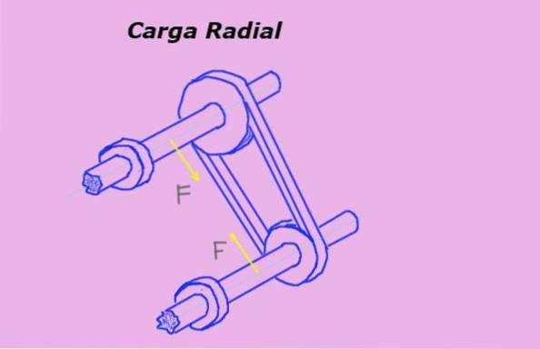
The radial load It is the force that is exerted perpendicular to the axis of symmetry of an object and whose line of action passes through this axis. For example, a belt on a pulley imposes a radial load on the bearing or bearing of the pulley shaft..
In figure 1 the yellow arrows represent radial forces or loads on the shafts due to the tension of the belt passing through the pulleys.
The unit of measurement for radial load in the international or SI system is the Newton (N). But other units of force are also frequently used to measure it, such as the kilogram-force (Kg-f) and the pound-force (lb-f).
Article index
To calculate the value of the radial load on the elements of a structure, the following steps must be followed:
- Make the diagram of forces on each element.
- Apply the equations that guarantee translational equilibrium; that is, that the sum of all the forces is zero.
- Consider the equation of torques or moments so that rotational equilibrium is satisfied. In this case the sum of all torques must be zero.
- Calculate the forces to be able to identify the radial loads that act on each of the elements.
The following figure shows a pulley through which a tensioned pulley passes with tension T. The pulley is mounted on a shaft supported by two bearings. The center of one of them is at a distance L1 from the center of the pulley. At the other end is the other bearing, at distance Ltwo.
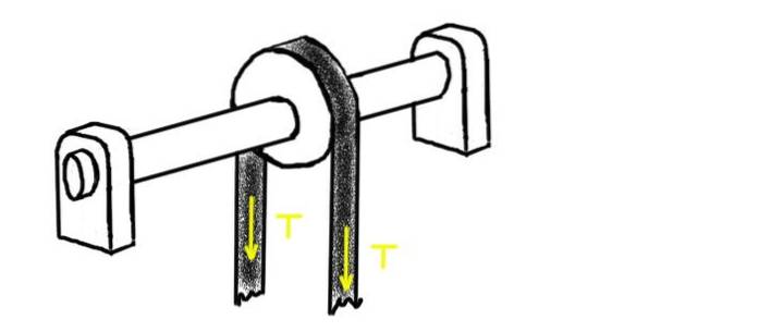
Determine the radial load on each of the bearings, assuming that the weight of the shaft and pulley are significantly less than the applied stress.
Take as value for the belt tension 100 kg-f and for the distances L1= 1 m and Ltwo= 2 m.
First, a diagram of the forces acting on the axis is made.
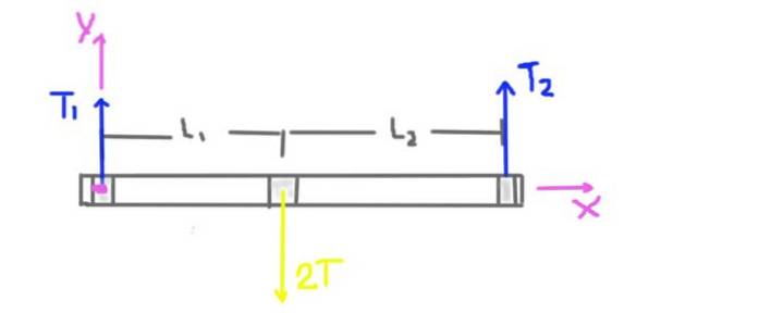
The pulley tension is T, but the radial load on the shaft at the pulley position is 2T. The weight of the shaft and the pulley is not taken into account because the statement of the problem tells us that it is considerably less than the tension applied to the belt.
The radial reaction of the supports on the shaft is caused by the radial forces or loads T1 and T2. The distances L1 and L2 from the supports to the center of the pulley are also indicated in the diagram..
The coordinate system is also displayed. The torque or total moment on the axis will be calculated taking as the center the origin of the coordinate system and will be positive in the Z direction.
Now the equilibrium conditions are established: sum of forces equal zero and sum of torques equal zero.
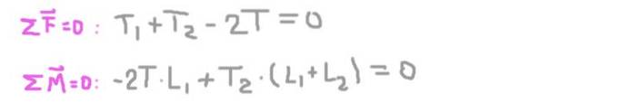
From the second equation we obtain the radial reaction on the axis in the support 2 (Ttwo), substituting in the first and solving for the radial reaction on the axis at support 1 (T1).
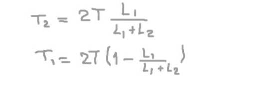
T1= (2/3) T = 66.6 kg-f
And the radial load on the shaft in the position of the support 2 is:
Ttwo= (4/3) T = 133.3 kg-f.
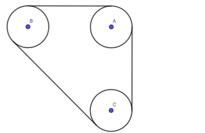
The following figure shows a system made up of three pulleys A, B, C all of the same radius R. The pulleys are connected by a belt that has a tension T.
Shafts A, B, C go through lubricated bearings. The separation between the centers of axes A and B is 4 times the radius R. Similarly, the separation between axes B and C is also 4R.
Determine the radial load on the axes of pulleys A and B, assuming the belt tension is 600N.
We begin by drawing a diagram of the forces that act on pulley A and on B. On the first we have the two tensions T1 and Ttwo, as well as the force FTO that the bearing exerts on the axis A of the pulley.
Similarly, on pulley B we have the tensions T3 , T4 and the force FB that the bearing exerts on the shaft of the same. The radial load on the axis of the pulley A is the force FTO and the radial load on the B is the force FB.
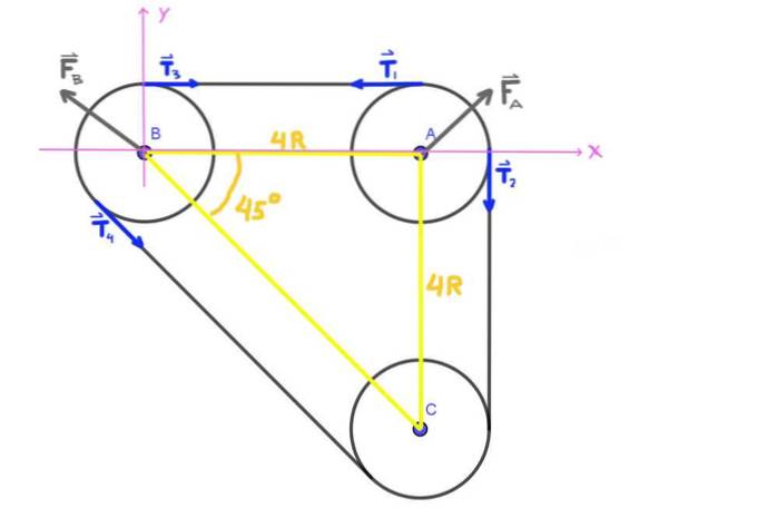
Since axes A, B, C form an isorectangle triangle, angle ABC is 45 °.
All voltages T1 , Ttwo , T3 , T4 shown in the figure have the same modulus T, which is the belt tension.
Now we write the equilibrium condition for pulley A which is nothing other than the sum of all the forces that act on pulley A must be zero.
Separating the X and Y components of the forces and adding (vectorially) the following pair of scalar equations is obtained:
FTOX - T = 0; FTOY - T = 0
These equations lead to the following equality: FAX = FOH = T.
Therefore the radial load has magnitude given by:
FTO = (T² + T²)1/2 = 21/2∙ T = 1.41 ∙ T = 848.5 N. with 45 ° direction.
Similarly, we write the equilibrium condition for pulley B. For component X we have: FBX + T + T ∙ Cos45 ° = 0
Y for component Y: FBY + T ∙ Sen45 ° = 0
Thus:
FBX = - T (1 + 2-1/2) and FBY = -T ∙ 2-1/2
That is, the magnitude of the radial load on pulley B is:
FB = ((1 + 2-1/2) ² + 2-1)1/2∙ T = 1.85 ∙ T = 1108.66 N and its direction is 135 °.


Yet No Comments