
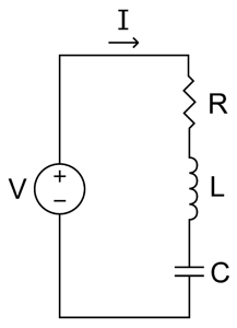
A series circuit It is one in which the connection of the elements is made one followed by the other; that is, in sequence. In these circuits the electric current circulates through a single path, from the source of energy to the components that make up the assembly (resistors, capacitors, inductors, switches, etc.).
The series circuit consists of a circulation mesh through which voltage drops and current consumption are registered depending on the energy demands of the connected components..
Article index
Series circuits have a general connection in sequence. This gives them certain technical specifications, which are detailed below:
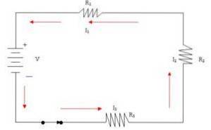
The output terminal of one element (negative) is linked to the input terminal of the next component (positive).
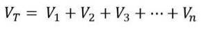
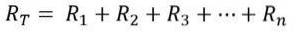
In case there is only one voltage source, then the voltage applied to the system will be equal to the sum of the voltage drops in each element of the circuit..
Thus, the mathematical expression used for this phenomenon is the following:
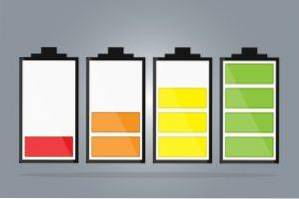
In the case of the connection of multiple batteries, when connecting two batteries the result obtained is the sum of both voltages.
The above occurs as long as both power sources are connected with the proper polarity; that is, the negative of the first battery with the positive of the second battery, and so on.
This is because the current does not divide into any branch, since everything circulates through the same path.
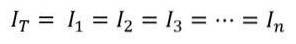
This means that the same intensity of the current passes through each and every one of the elements connected in the series assembly..
Since the intensity of the current follows a single path of circulation, the total resistance of the circuit is equal to the sum of all the resistances that compose it.
Mathematically, this principle is expressed as follows:
The more resistors connected to the circuit, the greater the total equivalent resistance of the system and, according to Ohm's Law (V = I * R), if the resistance increases, then the intensity decreases..
In short, the more resistors we connect to the circuit in series, the lower the current that flows through it..
For example, if the circuit includes the connection of a switch and it opens, the current automatically stops flowing through the circuit, regardless of the disconnection point..
The same happens if one of the elements breaks down during its operation. If a component melts or disconnects, then the circuit will open at that point and current will stop flowing..
Furthermore, the nature of the circuit implies that all components are connected or disconnected simultaneously.
That is, either the circuit is open (and therefore all components are disconnected) or the circuit is closed (and consequently all components are connected).
A series circuit is driven by a voltage generating source, which induces current to flow through the entire circuit..
In turn, in order to circulate the current, it needs a closed path that allows it to go through a closed circuit and return to the voltage source through its negative terminal..
Regardless of the variations of each circuit, roughly all series circuits are made up of:
- A source of power.
- A conductive material (cable) that facilitates the circulation of current and that closes the circuit in all its points.
- One or more receiving elements that absorb the energy provided by the power source: resistors, inductors, capacitors and other electronic components.
The configuration of a series circuit is very simple, and the assembly can be replicated at home with very few tools.
Here is a practical guide on how to assemble a series circuit quickly and efficiently:
1- Select a base for the circuit, preferably wooden, to act as an insulating surface.
2- Locate the power source. Take a conventional battery and fasten it to the base of the circuit with adhesive tape, look for the assembly to remain fixed.
3- Fix the light bulb holders on the base of the circuit with a screw. These elements will act as the mounting resistors. You can place as many bulb holders as resistors you want to connect in the circuit.
4- Locate the switch on the base of the circuit, right next to the positive polarity. In this way, the switch actuates the flow of current through the circuit, closing the connection.
5- Cut the copper cables to size, according to the distances established between the various components of the circuit. Remember to remove the conductor coating at the ends, using a specialized pick ax..
6- Make the connections between the various elements that make up the circuit.
7- When finished, press the switch to certify the operation of the electrical assembly.
Series circuits come in various configurations in everyday life; are an intrinsic part of everyday life.
A palpable example of this is the Christmas lights, in whose assembly the power supply is given by the current socket (power source), followed by the conductors and passing through the bulbs (resistors).

Likewise, when connecting the batteries into a flashlight, the batteries are connected in series; that is, one after the other, alternately connecting the positive and negative poles of each battery. Thus, the total battery voltage is the sum of the voltages of all the batteries.


Yet No Comments