The moody diagram consists of a series of curves drawn on logarithmic paper, which are used to calculate the friction factor present in the flow of a turbulent fluid through a circular duct.
With friction factor F friction energy loss is evaluated, an important value to determine the proper performance of pumps that distribute fluids such as water, gasoline, crude oil and others.

To know the energy in the flow of a fluid, it is necessary to know the gains and losses due to factors such as speed, height, the presence of devices (pumps and motors), the effects of fluid viscosity and friction between it. and the walls of the pipe.
Article index
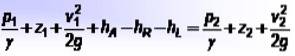
- p1 Y ptwo are the pressures at each point,
- z1 Y ztwo are the heights with respect to reference point,
- v1 Y vtwo are the respective fluid velocities,
- hTO is the energy added by pumps, hR is the energy taken by some device such as a motor, and hL covers fluid energy losses due to friction between the fluid and pipe walls, as well as other minor losses.
The value of hL is calculated using the Darcy-Weisbach equation:
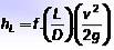
Where L is the length of the pipe, D is its inside diameter, v is the velocity of the fluid and g is the value of the acceleration due to gravity. The dimensions of hL are length, and usually the units in which it is represented are meters or feet.
To calculate F empirical equations obtained from experimental data can be used. It is necessary to distinguish whether it is a fluid in a laminar regime or in a turbulent regime. For the laminar regimen F easily evaluated:
f = 64 / NR
Where NR is the Reynolds number, whose value depends on the regime in which the fluid is. The criteria is:
Laminar flow: NR < 2000 el flujo es laminar; Flujo turbulento NR > 4000; Transitional regime: 2000 < NR < 4000
The Reynolds number (dimensionless) in turn depends on the speed of the fluid v, the internal diameter of the pipe D and the kinematic viscosity n of the fluid, whose value is obtained by means of tables:
NR = v.D / n
For a turbulent flow the most accepted equation in copper and glass pipes is that of Cyril Colebrook (1910-1997), but it has the disadvantage that F it is not explicit:
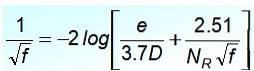
In this equation the quotient e / D is the relative roughness of the pipe and NR is the Reynolds number. A careful observation shows that it is not easy to let F to the left side of the equality, so it is not suitable for immediate calculations.
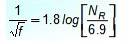
Colebrook himself suggested this approach, which is explicit, valid with some limitations:
The Moody diagram is useful for finding the friction factor F included in Darcy's equation, since in Colebrook's equation it is not easy to express F directly in terms of other values.
Its use simplifies obtaining the value of F, by containing the graphical representation of F in function of NR for different values of relative roughness on a logarithmic scale.
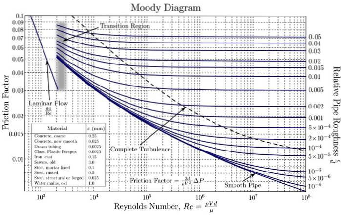
These curves have been created from experimental data with various materials commonly used in pipe fabrication. Using a logarithmic scale for both F as for NR it is necessary, since they cover a very wide range of values. In this way, the graphing of values of different orders of magnitude is facilitated..
The first graph of the Colebrook equation was obtained by the engineer Hunter Rouse (1906-1996) and soon after it was modified by Lewis F. Moody (1880-1953) in the form in which it is used today..
It is used for both circular and non-circular pipes, simply substituting the hydraulic diameter for these.
As explained above, the Moody diagram is made from numerous experimental data, presented in graphical form. Here are the steps to use it:
- Calculate Reynolds number NR to determine if the flow is laminar or turbulent.
- Calculate the relative roughness using the equation andr = e / D, where and is the absolute roughness of the material and D is the internal diameter of the pipe. These values are obtained through tables.
- Now that you have andr Y NR, project vertically until reaching the curve corresponding to the andr obtained.
- Project horizontally and to the left to read the value of F.
An example will help to easily visualize how the diagram is used.
Determine the friction factor for water at 160º F flowing at a rate of 22 ft / s in a duct made of uncoated wrought iron and 1-inch internal diameter..
Required data (found in tables):
Kinematic Viscosity of Water at 160ºF: 4.38 x 10⁻⁶ foottwo/ s
Absolute roughness of uncoated wrought iron: 1.5 x 10 -4 feet
The Reynolds number is calculated, but not before passing the internal diameter from 1 inch to feet:
1 inch = 0.0833 feet
NR = (22 x 0.0833) / 4.38 x 10-6= 4.18 x 10 5
According to the criteria shown before, it is a turbulent flow, then the Moody diagram allows obtaining the corresponding friction factor, without having to use the Colebrook equation.
You have to find the relative roughness:
andr = 1.5 x 10 -4 / 0.0833 = 0.0018
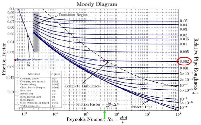
In the supplied Moody diagram, it is necessary to go to the extreme right and find the closest relative roughness to the value obtained. There is no one that corresponds exactly to 0.0018 but there is one that is quite close, that of 0.002 (red oval in the figure).
Simultaneously, the corresponding Reynolds number is searched on the horizontal axis. The closest value to 4.18 x 10 5 is 4 x 10 5 (green arrow in the figure). The intersection of both is the fuchsia point.
Project to the left following the blue dotted line and reach the orange point. Now estimate the value of F, taking into account that the divisions are not the same size as they are a logarithmic scale on both the horizontal and vertical axes.
The Moody diagram provided in the figure does not have fine horizontal divisions, therefore the value of F in 0.024 (it is between 0.02 and 0.03 but it is not half but a little less).
There are calculators online that use the Colebrook equation. One of them (see References) supplied the value 0.023664639 for the friction factor.
The Moody diagram can be applied to solve three types of problems, provided the fluid and the absolute roughness of the pipe are known:
- Calculation of the pressure drop or the pressure difference between two points, provided the length of the pipe, the difference in height between the two points to be considered, the velocity and the internal diameter of the pipe.
- Determination of the flow, knowing the length and diameter of the pipe, plus the specific pressure drop.
- Evaluation of the diameter of the pipe when the length, flow and pressure drop between the points to be considered are known.
Problems of the first type are solved directly by using the diagram, while those of the second and third types require the use of a computer package. For example, in the third type, if the diameter of the pipe is not known, the Reynolds number cannot be evaluated directly, nor the relative roughness.
One way to solve them is to assume an initial internal diameter and from there successively adjust the values to obtain the pressure drop specified in the problem..
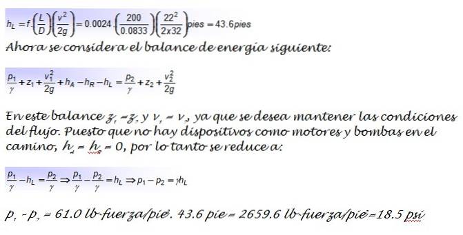
You have 160 ° F water flowing steadily along a 1-inch diameter uncoated wrought iron pipe at a rate of 22 ft / s. Determine the pressure difference caused by friction and the pumping power required to maintain flow in a length of horizontal pipe L = 200 feet long..
Data needed: acceleration of gravity is 32 ft / stwo ; the specific gravity of water at 160ºF is γ = 61.0 lb-force / ft3
This is the pipe from solved example 1, therefore the friction factor is already known F, which has been estimated at 0.0024. This value is taken into the Darcy equation to evaluate friction losses:
The required pumping power is:
W = v. A. (p1 - ptwo)
Where A is the cross-sectional area of the tube: A = p. (Dtwo/ 4) = p. (0.0833two/ 4) foottwo = 0.00545 foottwo
W = 22 ft / s. 2659.6 lb-force / fttwo. 0.00545 fttwo= 318.9 lb-force. feet
Power is best expressed in Watts, for which the conversion factor is required:
1 Watt = 0.737 lb-force. feet
Therefore the power required to maintain the flow is W = 432.7 W


Yet No Comments