
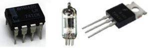
The active filters They are those that have controlled sources or active elements, such as operational amplifiers, transistors or vacuum tubes. Through an electronic circuit, a filter allows to fulfill the modeling of a transfer function that changes the input signal and gives an output signal according to the design.
The configuration of an electronic filter is usually selective and the selection criterion is the frequency of the input signal. Due to the above, depending on the type of circuit (in series or in parallel) the filter will allow the passage of certain signals and will block the passage of the rest..
In this way, the output signal will be characterized by being refined according to the design parameters of the circuit that constitutes the filter..
Article index
- Active filters are analog filters, which means that they modify an analog signal (input) based on the frequency components.
- Thanks to the presence of active components (operational amplifiers, vacuum tubes, transistors, etc.), this type of filter increases a section or the entire output signal, with respect to the input signal..
This is due to power amplification by the use of operational amplifiers (OPAMS). This facilitates obtaining resonance and a high quality factor, without the need to use inductors. For its part, the quality factor -also known as the Q factor- is a measure of the acuity and efficiency of the resonance..
- Active filters can combine active and passive components. The latter are the basic components of circuits: resistors, capacitors and inductors..
- Active filters allow cascade connections, are configured to amplify signals and allow integration between two or more circuits if necessary.
- In case the circuit has operational amplifiers, the output voltage of the circuit is limited by the saturation voltage of these elements.
- Depending on the type of circuit, and the ratings of the active and passive elements, the active filter can be designed to provide a high input impedance and a small output impedance..
- The manufacture of active filters is economical compared to other types of assemblies.
- To operate, active filters require a power supply, preferably symmetrical.
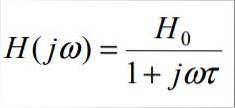
First-order filters are used to attenuate signals above or below the degree of rejection, in multiples of 6 decibels each time the frequency is doubled. This type of montage is usually represented by the following transfer function:
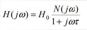
When breaking down the numerator and denominator of the expression, we have:
- N (jω) is a polynomial of degree ≤ 1
- t is the inverse of the angular frequency of the filter
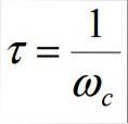
- Wc is the angular frequency of the filter, and is given by the following equation:
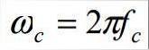
In this expression fc is the filter cutoff frequency.
The cutoff frequency is that limit frequency of the filter for which an attenuation of the signal is induced. Depending on the filter configuration (low pass, high pass, band pass or eliminate bands), the effect of the filter design is presented precisely from the cutoff frequency..
In the particular case of first order filters, these can only be low pass or high pass.
This type of filter allows the lower frequencies to pass through, and attenuates or suppresses frequencies above the cutoff frequency..
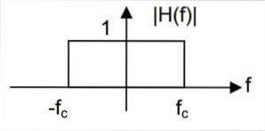
The transfer function for the low pass filters is as follows:
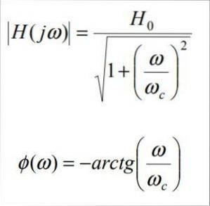
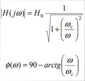
The amplitude and phase response of this transfer function is:
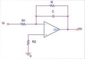
An active low-pass filter can fulfill the design function by employing input and grounding resistors, along with op-amps and parallel capacitor and resistor configurations. An example of an active low-pass inverter circuit is presented below:
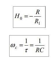
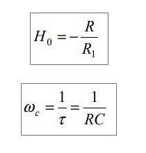
The parameters of the transfer function for this circuit are:
For their part, high-pass filters have the opposite effect, compared to low-pass filters. In other words, this type of filter attenuates the low frequencies and lets the high frequencies pass..
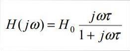
Even, depending on the circuit configuration, active high-pass filters can amplify the signals if they have operational amplifiers specially arranged for that purpose. The transfer function of a first-order active high-pass filter is as follows:
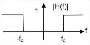
The amplitude and phase response of the system is:
An active high pass filter employs resistors and capacitors in series at the input of the circuit, as well as a resistor in the discharge path to ground, to serve as a feedback impedance. Here is an example of an active high pass inverter circuit:
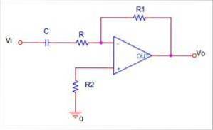
The parameters of the transfer function for this circuit are:
Second order filters are usually obtained by making connections of first order filters in series, to obtain a more complex assembly that allows to selectively tune frequencies.
The general expression for the transfer function of a second order filter is:
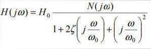
When breaking down the numerator and denominator of the expression, we have:
- N (jω) is a polynomial of degree ≤ 2.
- Wor is the angular frequency of the filter, and is given by the following equation:
In this equation for is the characteristic frequency of the filter. In case of having an RLC circuit (resistance, inductor and capacitor in series), the characteristic frequency of the filter matches the resonance frequency of the filter.
In turn, the resonant frequency is the frequency at which the system reaches its maximum degree of oscillation..
- ζ is the damping factor. This factor defines the ability of the system to dampen the input signal.
In turn, from the damping factor, the filter quality factor is obtained through the following expression:
Depending on the design of the circuit impedances, the second order active filters can be: low pass filters, high pass filters and band pass filters.
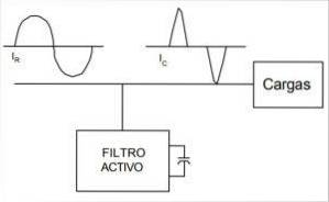
Active filters are used in electrical networks in order to reduce disturbances in the network, due to the connection of non-linear loads.
These disturbances can be permeated by combining active and passive filters, and varying the input impedances and RC settings throughout the assembly..
In power electrical networks, active filters are used to reduce harmonics of current that circulate through the network between the active filter and the electrical power generation node..
Likewise, active filters help to balance the return currents that circulate through the neutral, and the harmonics associated with this current flow and the system voltage..
In addition, active filters play an excellent role in correcting the power factor of interconnected electrical systems..

Yet No Comments