
The inductance It is the property of electrical circuits by which an electromotive force is produced, due to the passage of electric current and the variation of the associated magnetic field. This electromotive force can generate two well differentiated phenomena..
The first is a proper inductance in the coil, and the second corresponds to a mutual inductance, if it is two or more coils coupled to each other. This phenomenon is based on Faraday's Law, also known as the law of electromagnetic induction, which indicates that it is feasible to generate an electric field from a variable magnetic field..
In 1886 the English physicist, mathematician, electrical engineer and radio operator Oliver Heaviside gave the first indications about self-induction. Later, the American physicist Joseph Henry also made important contributions on electromagnetic induction; therefore the inductance measurement unit bears his name.
Likewise, the German physicist Heinrich Lenz postulated Lenz's law, which states the direction of the induced electromotive force. According to Lenz, this force induced by the difference in voltage applied to a conductor goes in the opposite direction to the direction of the current flowing through it..
Inductance is part of the impedance of the circuit; that is, its existence implies a certain resistance to the flow of current.
Article index
Inductance is usually represented with the letter "L", in honor of the contributions of the physicist Heinrich Lenz on the subject.
The mathematical modeling of the physical phenomenon involves electrical variables such as the magnetic flux, the potential difference and the electric current of the study circuit..
Mathematically, the formula for magnetic inductance is defined as the quotient between the magnetic flux in the element (circuit, electric coil, loop, etc.), and the electric current that circulates through the element.
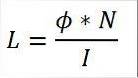
In this formula:
L: inductance [H].
Φ: magnetic flux [Wb].
I: intensity of electric current [A].
N: number of winding coils [unitless].
The magnetic flux that is mentioned in this formula is the flux produced solely due to the circulation of electric current.
For this expression to be valid, other electromagnetic fluxes generated by external factors such as magnets, or electromagnetic waves outside the study circuit should not be considered..
The value of the inductance is inversely proportional to the intensity of the current. This means that the higher the inductance, the lower the current flow through the circuit, and vice versa..
For its part, the magnitude of the inductance is directly proportional to the number of turns (or turns) that make up the coil. The more spirals the inductor has, the greater the value of its inductance.
This property also varies depending on the physical properties of the conductive wire that makes up the coil, as well as the length of the coil..
Magnetic flux related to a coil or conductor is a difficult variable to measure. However, it is feasible to obtain the electric potential differential caused by the variations in said flow..
This last variable is nothing more than the electrical voltage, which is a measurable variable through conventional instruments such as a voltmeter or a multimeter. Thus, the mathematical expression that defines the voltage at the terminals of the inductor is the following:
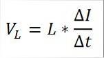
In this expression:
VL: potential difference across the inductor [V].
L: inductance [H].
∆I: current differential [I].
∆t: time differential [s].
If it is a single coil, then the VL is the self-induced voltage of the inductor. The polarity of this voltage will depend on whether the magnitude of the current increases (positive sign) or decreases (negative sign) when circulating from one pole to another..
Finally, when solving the inductance of the previous mathematical expression, we have the following:
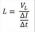
The magnitude of the inductance can be obtained by dividing the value of the self-induced voltage by the differential of the current with respect to time.
The materials of manufacture and the geometry of the inductor play a fundamental role in the value of the inductance. That is, in addition to the intensity of the current, there are other factors that affect it.
The formula that describes the inductance value as a function of the physical properties of the system is as follows:
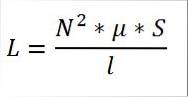
In this formula:
L: inductance [H].
N: number of turns of the coil [without unit].
µ: magnetic permeability of the material [Wb / A · m].
S: cross-sectional area of the core [mtwo].
l: length of flow lines [m].
The magnitude of the inductance is directly proportional to the square of the number of turns, the cross-sectional area of the coil, and the magnetic permeability of the material..
For its part, magnetic permeability is the property of the material to attract magnetic fields and be traversed by them. Each material has a different magnetic permeability.
In turn, the inductance is inversely proportional to the length of the coil. If the inductor is very long, the inductance value will be less.
In the international system (SI) the unit of inductance is the henry, in honor of the American physicist Joseph Henry.
According to the formula to determine the inductance as a function of the magnetic flux and the intensity of the current, we have to:
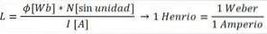
On the other hand, if we determine the measurement units that make up the henry based on the inductance formula as a function of the induced voltage, we have:
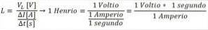
It is worth noting that, in terms of the unit of measurement, both expressions are perfectly equivalent. The most common magnitudes of inductances are usually expressed in millihenries (mH) and microhenries (μH).
Self-induction is a phenomenon that occurs when an electric current circulates through a coil and this induces an intrinsic electromotive force in the system..
This electromotive force is called voltage or induced voltage, and it arises as a result of the presence of a variable magnetic flux.
The electromotive force is proportional to the rate of change of the current flowing through the coil. In turn, this new voltage differential induces the circulation of a new electric current that goes in the opposite direction to the primary current of the circuit..
Self-inductance occurs as a result of the influence that the assembly exerts on itself, due to the presence of variable magnetic fields.
The unit of measurement of self-inductance is also the henry [H], and it is usually represented in the literature with the letter L.
It is important to differentiate where each phenomenon occurs: the temporal variation of the magnetic flux occurs on an open surface; i.e. around the coil of interest.
Instead, the electromotive force induced in the system is the potential difference existing in the closed loop that demarcates the open surface of the circuit..
In turn, the magnetic flux that passes through each turn of a coil is directly proportional to the intensity of the current that causes it..
This proportionality factor between the magnetic flux and the intensity of the current is what is known as the coefficient of self-induction, or what is the same, the self-inductance of the circuit..
Given the proportionality between both factors, if the intensity of the current varies as a function of time, then the magnetic flux will have a similar behavior.
Thus, the circuit presents a change in its own current variations, and this variation will be greater and greater as the intensity of the current varies significantly..
Self-inductance can be understood as a kind of electromagnetic inertia, and its value will depend on the geometry of the system, provided that the proportionality between the magnetic flux and the intensity of the current is fulfilled..
Mutual inductance comes from the induction of an electromotive force in a coil (coil No. 2), due to the circulation of an electric current in a nearby coil (coil No. 1).
Therefore, mutual inductance is defined as the ratio factor between the electromotive force generated in coil No. 2 and the variation of current in coil No. 1.
The unit of measurement for mutual inductance is the henry [H] and it is represented in the literature with the letter M. Thus, mutual inductance is that which occurs between two coils coupled to each other, since the flow of current through of one coil produces a voltage across the terminals of the other.
The phenomenon of induction of an electromotive force in the coupled coil is based on Faraday's law.
According to this law, the induced voltage in a system is proportional to the rate of change of the magnetic flux in time.
For its part, the polarity of the induced electromotive force is given by Lenz's law, according to which this electromotive force will oppose the circulation of the current that produces it..
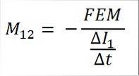
The electromotive force induced in coil No. 2 is given by the following mathematical expression:
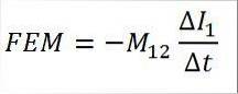
In this expression:
EMF: electromotive force [V].
M12: mutual inductance between coil No. 1 and coil No. 2 [H].
∆I1: current variation in coil N ° 1 [A].
∆t: temporal variation [s].
Thus, when solving the mutual inductance of the previous mathematical expression, the following results:
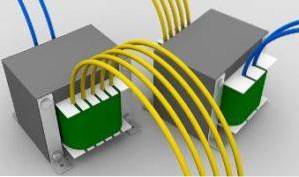
The most common application of mutual inductance is the transformer.
For its part, it is also possible to deduce the mutual inductance by obtaining the quotient between the magnetic flux between both coils and the intensity of the current that circulates through the primary coil..
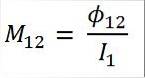
In this expression:
M12: mutual inductance between coil No. 1 and coil No. 2 [H].
Φ12: magnetic flux between coils No. 1 and No. 2 [Wb].
I1: intensity of electric current through coil N ° 1 [A].
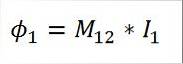
When evaluating the magnetic fluxes of each coil, each of these is proportional to the mutual inductance and the current of that coil. Then, the magnetic flux associated with coil N ° 1 is given by the following equation:
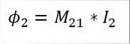
Similarly, the magnetic flux inherent in the second coil will be obtained from the following formula:
The value of the mutual inductance will also depend on the geometry of the coupled coils, due to the proportional relationship to the magnetic field that passes through the cross sections of the associated elements..
If the geometry of the coupling remains constant, the mutual inductance will also remain unchanged. Consequently, the variation of the electromagnetic flux will only depend on the intensity of the current.
According to the principle of reciprocity of the media with constant physical properties, the mutual inductances are identical to each other, as detailed in the following equation:
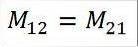
That is, the inductance of coil No. 1 in relation to coil No. 2 is equal to the inductance of coil No. 2 in relation to coil No. 1.
Magnetic induction is the basic principle of action of electrical transformers, which allow raising and lowering voltage levels at a constant power.
The flow of current through the primary winding of the transformer induces an electromotive force in the secondary winding which, in turn, results in the circulation of an electric current.
The transformation ratio of the device is given by the number of turns of each winding, with which it is feasible to determine the secondary voltage of the transformer.
The product of voltage and electrical current (that is, power) remains constant, except for some technical losses due to the inherent inefficiency of the process.


Yet No Comments