The Faraday's law in electromagnetism states that a changing magnetic field flux is capable of inducing an electric current in a closed circuit.
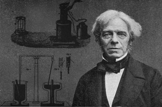
In 1831, the English physicist Michael Faraday experimented with moving conductors within a magnetic field and also varying magnetic fields that passed through fixed conductors..
Faraday realized that if he varied the magnetic field flux over time, he was able to establish a voltage proportional to that variation. If ε is the voltage or induced electromotive force (induced emf) and Φ is the magnetic field flux, in mathematical form it can be expressed:
| ε | = ΔΦ / Δt
Where the symbol Δ indicates variation of the quantity and the bars in the emf indicate the absolute value of this. Since it is a closed circuit, the current can flow in one direction or the other.
Magnetic flux, produced by a magnetic field across a surface, can vary in a number of ways, for example:
-Moving a bar magnet through a circular loop.
-Increasing or decreasing the intensity of the magnetic field that passes through the loop.
-Leaving the field fixed, but by means of some mechanism change the area of the loop.
-Combining the above methods.
Article index
Suppose that you have a closed circuit of area A, such as a circular loop or winding equal to the one in figure 1, and that you have a magnet that produces a magnetic field B.
The magnetic field flux Φ is a scalar quantity that refers to the number of field lines that cross area A. In figure 1 are the white lines that leave the north pole of the magnet and return through the south.
The intensity of the field will be proportional to the number of lines per unit area, so we can see that at the poles it is very intense. But we can have a very intense field that does not produce flux in the loop, which we can achieve by changing the orientation of this (or the magnet).
To take into account the orientation factor, the magnetic field flux is defined as the scalar product between B Y n, being n the unit normal vector to the surface of the loop and that indicates its orientation:
Φ = B•n A = BA.cosθ
Where θ is the angle between B Y n. If for example B Y n are perpendicular, the magnetic field flux is zero, because in that case the field is tangent to the plane of the loop and cannot pass through its surface.
Instead yes B Y n are parallel, it means that the field is perpendicular to the plane of the loop and the lines pass through it as far as possible.
The unit in the International System for F is the weber (W), where 1 W = 1 T.mtwo (read "tesla per square meter").
In figure 1 we can see that the polarity of the voltage changes as the magnet moves. Polarity is established by Lenz's law, which states that the induced voltage must oppose the variation that produces it.
If, for example, the magnetic flux produced by the magnet increases, a current is established in the conductor that circulates creating its own flux, which opposes this increase..
If, on the contrary, the flux created by the magnet decreases, the induced current circulates in such a way that its own flux counteracts said decrease..
To take this phenomenon into account, a negative sign is placed before Faraday's law and it is no longer necessary to place the absolute value bars:
ε = -ΔΦ / Δt
This is the Faraday-Lenz law. If the flow variation is infinitesimal, the deltas are replaced by differentials:
ε = -dΦ / dt
The above equation is valid for a loop. But if we have a coil of N turns, the result is much better, because the emf is multiplied N times:
ε = - N (dΦ / dt)
For the current to turn on the bulb to be produced, there must be relative movement between the magnet and the loop. This is one of the ways in which the flux can vary, because in this way the intensity of the field passing through the loop changes..
As soon as the movement of the magnet ceases, the bulb goes out, even if the magnet is left still in the middle of the loop. What is needed to circulate the current that turns on the bulb is that the field flux varies.
When the magnetic field varies with time, we can express it as:
B = B (t).
By keeping the area A of the loop constant and leaving it fixed at a constant angle, which in the case of the figure is 0º, then:
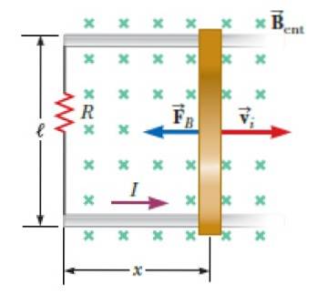
If it is possible to change the area of the loop, leaving its orientation fixed and placing it in the middle of a constant field, the induced emf is given by:
One way to achieve this is to put a bar that slides on a conductor rail at a certain speed, as shown in the following figure.
The bar and the rail, plus a light bulb or a resistor connected with conductive wires, form a closed circuit in the shape of a rectangular loop..
When sliding the bar, the length x increases or decreases, and with it the area of the loop changes, which is enough to create a variable flow.
As we said before, if the angle between B and the normal of the loop is made to vary, the field flux changes according to:
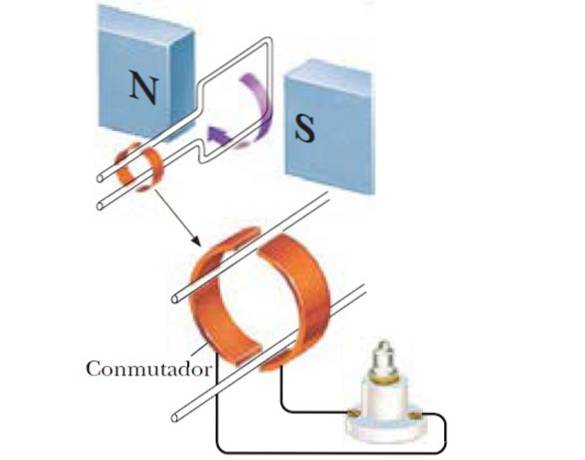
Thus, a sinusoidal generator is obtained, and if instead of a single coil a number N of coils are used, the induced emf is greater:

A circular coil of N turns and radius R, rotates with angular frequency ω in the middle of a magnetic field of magnitude B. Find an expression for the maximum emf induced in the coil.
The expression for the emf induced by rotation is applied when the coil has N turns, knowing that:
-The area of the coil is A = πRtwo
-The angle θ varies as a function of time as θ = ωt
It is important to note that first θ = ωt is substituted in Faraday's law and soon is derived with respect to time:
ε = -NBA (cos θ) '= -NB (πRtwo). [cos (ωt)] '= NBω (πRtwo) sin (ωt)
Since the maximum emf is requested, it occurs whenever sin ωt = 1, so finally:
εmax = NBω (πRtwo)


Yet No Comments