The parallel port It is the part of a computer that is used to connect with different devices, sending or receiving information. This port is used for the purpose of transmitting data in parallel.
It is also known as the Centronics interface or connector, a name obtained thanks to the company that originally designed the standard for parallel communication between a computer and a printer. Later, the Epson brand designed a more modern parallel interface.
Most IBM-compatible personal computers have at least one parallel port and one serial port. They are located on the back of them, forming part of the motherboard.
The parallel port can directly transmit one byte by transferring eight bits at the same time over eight different wires. So it is faster compared to serial communication.
With the advent of the much faster USB port, the parallel port is now rarely used compared to how often it was used previously. In fact, the vast majority of newer microcomputers do not have a parallel port..
Article index
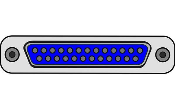
The parallel port is a hallmark of old computer technology: large and low speed. It uses a DB-25 connector, which is a 25-pin D-shaped connector, which is connected to power cables. Port is female, with 25 holes.
The transmission speed of a parallel port is quite high compared to a serial port. The parallel port has the ability to transmit multiple data streams at the same time. Sends data through multiple bits in parallel.
The number of cables that connect to the parallel port is quite high, when compared to the serial port.
To eliminate errors due to crosstalk, in parallel communication it is necessary that all data bit streams be transferred at the same speed. However, since this requirement becomes more difficult the longer the distance to be covered, it is preferred in this communication that the transmission cables have a short length..
Each pin is used to literally communicate 1 bit of information. That is, a pin without load is '0' and with load is '1'. All the pins can transmit information in parallel simultaneously, while through a serial port it is done in series (one to one).
The voltage level of a loaded pin is 5 volts and can be used to directly drive an LED. The parallel port pins are segmented into 3 sets for different purposes, which are:
The data set consists of 8 data pins (pins 2 to 9) that allow data to be transmitted or received from or to an external device.
Therefore, these pins are intended for data input and output, to generally send the information to be printed to the printer..
The control set consists of 8 pins that are used to control the sending and receiving of data. These pins are intended to send the control information to the printer.
The most important is the pin that indicates that the data is ready to be sent or received.
The status set is a read-only port made up of five input pins, one IRQ status register, and two reserved pins.
These pins are inputs that come from the printer to the PC, which are used to communicate states such as 'out of paper', 'error', 'busy', etc..
It can send 8 bits and receive 5 bits at a time. It is capable of sending 50 to 100 kilobytes of data per second. Pins 18 through 25, originally used as “ground” only, can also be used as data pins.
This enables full-duplex or bi-directional communication. This communication allows each device to receive and transmit data.
It was created in 1991 by Intel, Xircom, and Zenith. It supports bi-directional communication and transfer speeds ten times faster than the Centronics port. The EPP allows you to transfer much more data per second, from 500 kilobytes to 2 megabytes.
The parallel port provides an interface to connect multiple devices, preparing a parallel communication to send a large amount of data at the same time.
Currently, the parallel port has been largely replaced by the USB port. However, there is a list of different hardware components that used the parallel port, such as printers, hard drives, scanners, CD drives, etc..
The function of each pin is:
It remains at a value of 1, but changes to zero each time the computer issues a byte of data. A value of 0 notifies the printer that data is being transmitted.
They are used to transport the data. A load of 5 volts is sent to the corresponding pin to indicate that the bit has the value 1. If a pin has no load it indicates that its value is 0. This is a very effective and simple way to transfer digital information in real time through of an analog cable.
It is responsible for transmitting a confirmation signal from the printer to the computer. It stays on just like pin 1, lowering the voltage to 0 so that the computer knows that the data was received.
This pin will be on when the printer is busy. When idling it will change the voltage to 0 so that the computer is aware that it is ready to accept more data.
By sending a load to this pin, the printer notifies the computer that it is out of paper..
As long as the computer receives a load on this pin it will be aware that the device is online.
When this pin is turned on, the computer sends the automatic feed signal to the printer..
When the printer has a problem, lower the voltage to 0 volts on this pin so that the computer knows there is an error.
Every time a new print job is ready, the computer loads this pin to initialize the printer.
The computer uses this pin to remotely disconnect the printer. This is accomplished by sending this loaded pin to the printer and keeping it that way as long as you want the printer to be offline..
These pins are used as ground.


Yet No Comments