The voltage divider or voltage divider consists of an association of resistors or impedances in series connected to a source. In this way the voltage V supplied by the source -input voltage- is distributed proportionally in each element, according to Ohm's law:
Vi = I.Zi.
Where Vi is the voltage across the circuit element, I is the current flowing through it and Zi the corresponding impedance.
When arranging the source and the elements in a closed circuit, Kirchhoff's second law must be fulfilled, which states that the sum of all the voltage drops and rises is equal to 0.
For example, if the circuit to be considered is purely resistive and a 12-volt source is available, simply by placing two identical resistors in series with said source, the voltage will be divided: each resistance will have 6 Volts. And with three identical resistors, 4 V is obtained in each one.
Since the source represents a voltage rise, then V = +12 V. And in each resistor there are voltage drops that are represented by negative signs: - 6 V and - 6 V respectively. It is easy to see that Kirchoff's second law is fulfilled:
+12 V - 6 V - 6 V = 0 V
This is where the name of voltage divider comes from, because through series resistors, lower voltages can easily be obtained starting from a source with a higher voltage.
Article index
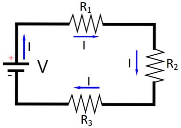
Let's continue considering a purely resistive circuit. We know that the current I that goes through a circuit of resistors in series connected to a source as shown in figure 1, is the same. And according to Ohm's law and Kirchoff's second law:
V = IR1 + TO GOtwo + TO GO3 +… TO GOi
Where R1, Rtwo… Ri represents each series resistance of the circuit. Therefore:
V = I ∑ Ri
So the current turns out to be:
I = V / ∑ Ri
Now let's calculate the voltage across one of the resistors, the resistor Ri for example:
Vi = (V / ∑ Ri) Ri
The above equation is rewritten as follows and we have the voltage divider rule ready for a battery and N resistors in series:
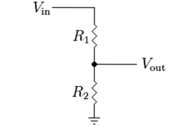
If we have a voltage divider circuit with 2 resistors, the above equation becomes:
And in the special case where R1 = Rtwo, Vi = V / 2, regardless of current, as stated at the beginning. This is the simplest voltage divider of all.
In the following figure is the diagram of this divider, where V, the input voltage, is symbolized as Vin, and Vi is the voltage obtained by dividing the voltage between the resistors R1 and Rtwo.
The voltage divider rule will be applied in two resistive circuits to obtain lower voltages.
A 12 V source is available, which has to be divided into 7 V and 5 V by means of two resistors R1 and Rtwo. There is a 100 Ω fixed resistance and a variable resistance whose range is between 0 and 1kΩ. What options are there to configure the circuit and set the value of the resistor Rtwo?
To solve this exercise, the rule of the voltage divider for two resistors will be used:
Suppose that R1 is the resistance found at a voltage of 7 V and there the fixed resistance R is placed1 = 100 Ω
The unknown resistance Rtwo must be at 5 V:
And R1 at 7 V:
5 (Rtwo +100) = 12 Rtwo
500 = 7 Rtwo
Rtwo = 71.43 Ω
Likewise, you can use the other equation to obtain the same value, or substitute the result obtained to check for equality.
If now the fixed resistance is placed as Rtwo, then it will be R1 is at 7 V:
5 (100 + R1) = 100 x 12
500 + 5R1 = 1200
R1 = 140 Ω
In the same way, it is possible to verify that this value satisfies the second equation. Both values are in the variable resistance range, therefore it is possible to implement the requested circuit in both ways.
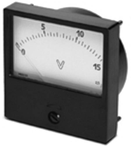
A DC direct current voltmeter to measure voltages in a certain range, is based on the voltage divider. To build such a voltmeter, a galvanometer is required, for example D'Arsonval's.
It is a meter that detects electrical currents, equipped with a graduated scale and an indicating needle. There are many models of galvanometers, the one in the figure is a very simple one, with two connection terminals that are on the back..
The galvanometer has an internal resistance RG, which tolerates only a small current, called maximum current IG. Consequently, the voltage across the galvanometer is Vm = IGRG.
To measure any voltage, the voltmeter is placed in parallel with the element to be measured and its internal resistance must be large enough not to draw current from the circuit, otherwise it will alter it..
If we want to use the galvanometer as a meter, the voltage to be measured must not exceed the maximum allowed, which is the maximum deflection of the needle that the device has. But we assume that Vm is small, since IG and RG they are.
However, when the galvanometer is connected in series with another resistor RS, call limiting resistance, we can extend the measurement range of the galvanometer from the small Vm up to a certain higher voltage ε. When this voltage is reached, the instrument needle experiences maximum deflection.
The design scheme is as follows:
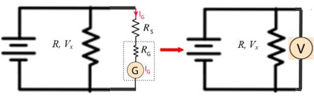
In figure 4 on the left, G is the galvanometer and R is any resistance over which you want to measure the voltage Vx.
The figure on the right shows how the circuit with G, RG and RS is equivalent to a voltmeter, which is placed in parallel to the resistance R.
For example, suppose the internal resistance of the galvanometer is RG = 50 Ω and the maximum current it supports is IG = 1 mA, the limiting resistance RS for the voltmeter built with this galvanometer to measure a maximum voltage of 1 V is calculated as follows:
IG (RS + RG) = 1 V
RS = (1 V / 1 x 10⁻³ A) - RG
RS = 1000 Ω - 50 Ω = 950 Ω


Yet No Comments