
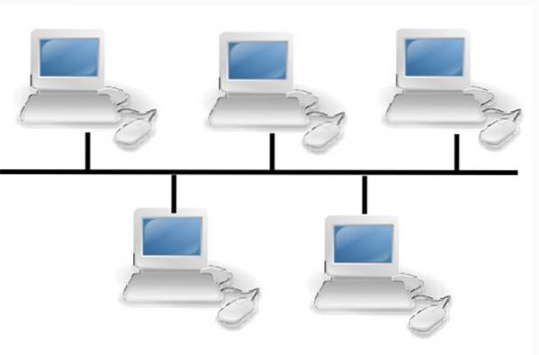
The bus topology is a configuration for a LAN or local area network in which all computers and devices on the network are connected to a single cable. This cable to which all nodes are connected is called the backbone network.
The bus topology does not require a lot of cabling and is relatively easy to install, compared to other alternatives. For example, this topology is used in Ethernet networks.
One way of considering a bus topology is that the line to which all the nodes or devices on the network are connected is like a corridor through which a signal travels to find the node to which it is going to be delivered..
The cable in the bus topology has two terminators that dampen the signal so that it does not continue to move from one end of the network to the other..
Bus topology is often valued for its simplicity and lower cost of implementation.
Article index
A bus topology is based on a main cable run where there is a terminator at each end. All devices, such as laptops, printers, servers, workstations, etc., are connected to the main cable.
Therefore, the main cable acts as the backbone of the entire network. Data sent by a computer is transmitted along the entire trunk cable in both directions from the sending computer.
When data arrives at a node, it checks the destination address (MAC / IP address) to see if it matches its address. If the address does not match, the node does nothing else. However, if the node address matches the address contained in the data, it processes the information.
Depending on the type of network card used in each computer, a coaxial cable or an RJ-45 network cable is used to connect them. Alternately known as line topology.
If the signal reaches the end of the cable length, it recovers and returns in the direction it came from. This is known as signal bounce..
This bounce of the signal will create a problem in the network, because if at the same time another signal is sent down the length of the cable, the two signals will collide.
Terminators are used to absorb the signal when it reaches the end, thus preventing the signal from bouncing.
It is the simplest network topology for connecting peripherals or computers. If the device has the appropriate connection mechanism, then it can be easily added to the network.
The new device connects and immediately becomes part of the network. For those who need a temporary network that can be set up quickly, there is no better option available.
If multiple users need access to a printer, adding it to the network immediately satisfies that need.
Compared to other network topologies, the bus topology is the cheapest to implement. This is because you need a shorter cable length.
Although terminators are required at both ends of the network to ensure proper operation, when a small network is required it is still affordable and easy to install.
This topology allows data to flow freely throughout the network. Although this limits external connections, it creates a local network that can work effectively with every connected computer..
Instead of hubs and switches a central server is used, which means there are fewer potential points of failure to manage.
The size and scope of this topology is limited. However, it can be extended quite easily.
Joining the cable with a repeater allows additional computers or peripherals to be added to the network. Although this could increase the number of package crashes that can occur, it is a simple solution with minimal total cost and helps to work quickly..
The terminators used for this topology are passive devices. They are made of resistors and capacitors, which means that there is no power requirement to meet.
This network is limited in size. Only a maximum number of devices and computers can be added to the network.
This limitation in its length increases the risk of collisions, because the space for communication is very important..
On the other hand, with a longer trunk cable other problems can occur, such as loss of data signal.
In addition, the problems in the quality of the data must be considered. When data signals collide with each other, the result is data loss, directly impacting the quality of communication..
Because every computer and peripheral connects via the trunk cable, adding devices will slow down the entire network by using just one cable..
This puts the entire network at risk if something happens to that cable. Damaged for any reason can cause the entire network to fail or split into two networks.
All data transmissions that occur in computers can be seen by any other computer connected to the backbone network.
This means that in this topology it is difficult to install security options, because what others are doing can be seen by everyone.
When there is an incorrect termination there may be communication problems. ISO 11898 requires terminators to be at both ends of the network trunk cable, which are mostly on the controlling device and on the device furthest from the controller.
A break in the backbone causes the entire network to collapse. Communication cannot be fully restored until the problem is repaired or the trunk cable is completely replaced..
A break event will cause any peripheral or computer to lose its communication with the devices on the other side of the network..
Computers on the network do not coordinate with each other regarding data transmission times.
This means that there can be multiple transmissions simultaneously, generating strong network traffic with a high probability of data loss..


Yet No Comments