A vector in space is everyone represented by a coordinate system given by x, Y Y z. Almost always the plane xy is the plane of the horizontal surface and the axis z represents height (or depth).
The Cartesian coordinate axes shown in figure 1 divide space into 8 regions called octants, analogous to how axes x - Y divide the plane into 4 quadrants. We will then have 1st octant, 2nd octant and so on.
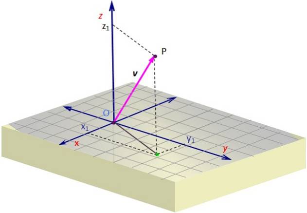
Figure 1 contains a representation of a vector v in the space. Some perspective is required to create the illusion of three dimensions on the plane of the screen, which is achieved by drawing an oblique view.
To graph a 3D vector, use the dotted lines that determine on the grid the coordinates of the projection or "shadow" of v Over the surface x-y. This projection begins at O and ends at the green point.
Once there, you have to continue along the vertical to the necessary height (or depth) according to the value of z, until reaching P. The vector is drawn starting from O and ending at P, which in the example is in the 1st octant.
Article index
Vectors in space are widely used in mechanics and other branches of physics and engineering, since the structures that surround us require geometry in three dimensions..
Position vectors in space are used to position objects relative to a reference point called source O. For this reason they are also necessary tools in navigation, but that is not all.
Forces acting on structures such as bolts, brackets, cables, struts, and more are vector in nature and oriented in space. In order to know its effect, it is necessary to know its address (and also its point of application).
And frequently the direction of a force is known by knowing two points in space that belong to its line of action. In this way the force is:
F = F or
Where F is the magnitude or modulus of the force and or is the unit vector (of modulus 1) directed along the line of action of F.
Before going on to solve some examples, we will briefly review 3D vector notation.
In the example in Figure 1, the vector v, whose point of origin coincides with the origin O and whose end is point P, has coordinates x Y z positive, while the coordinate Y is negative. These coordinates are: x1, Y1, z1, which are precisely the coordinates of P.
So if we have a vector linked to the origin, that is, whose starting point coincides with O, it is very easy to indicate its coordinates, which will be those of the extreme point or P. To distinguish between a point and a vector, we will use to the last bold letters and brackets, like this:
v = < x1, Y1, z1 >
While point P is denoted with parentheses:
P = (x1, Y1, z1)
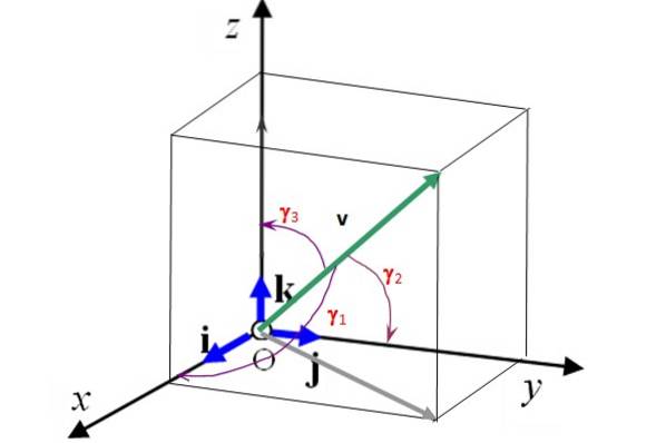
Another representation makes use of unit vectors i, j Y k that define the three directions of space on the axes x, Y Y z respectively.
These vectors are perpendicular to each other and form a orthonormal base (see figure 2). This means that a 3D vector can be written in terms of them as:
v = vx i + vY j + vz k
Figure 2 also shows the director angles γ1, γtwo and γ3 than vector v makes respectively with the axes x, Y Y z. Knowing these angles and the magnitude of the vector, it is completely determined. In addition, the cosines of the director angles meet the following relationship:
(cos γ1)two + (cos γtwo)two + (cos γ3)two = 1
In figure 2 the angles γ1, γtwo and γ3 than vector v of modulus 50 shape with the coordinate axes are respectively: 75.0º, 60.0º and 34.3º. Find the Cartesian components of this vector and represent it in terms of the unit vectors i, j Y k.
Vector projection v on the axis x is Vx = 50. cos 75º = 12,941. Similarly, the projection of v on the axis Y is VY = 50 cos 60 º = 25 and finally on the axis z is Vz = 50. cos 34.3º = 41.3. Now v can be expressed as:
v = 12.9 i + 25.0 j + 41.3 k
Find the tensions in each of the cables that hold the bucket in the figure that is in equilibrium, if its weight is 30 N.
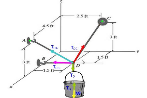
On the bucket, the free-body diagram indicates that TD (green) offsets the weight W (yellow), therefore TD = W = 30 N.
In the knot, the vector TD is directed vertically downwards, then:
TD = 30 (-k) N.
To establish the remaining voltages, follow these steps:
A = (4.5,0,3) (A is on the plane of the wall x-z)
B = (1.5,0,0) (B is on the x-axis)
C = (0, 2.5, 3) (C is on the plane of the wall and Z)
D = (1.5, 1.5, 0) (D is on the horizontal plane x-y)
GIVES = <3; -1.5; 3>
DC = <-1.5; 1; 3>
DB = <0; -1.5 ; 0>
A unit vector is obtained by the expression: or = r / r, with r (in bold) being the vector and r (not in bold) being the module of said vector.
DA = (3two + (-1.5)two + 3two)½ = 4.5; DC = ((-1.5) two + 1two + 3two)½ = 3.5
orGIVES = <3; -1.5; 3>4.5 = <0.67 ; -0.33 ; 0.67>
orDC = <-1.5; 1; 3>3.5 = <-0.43; 0.29; 0.86>
orDB = <0; -1; 0>
orD = <0; 0; -1>
TGIVES = TGIVES orGIVES = TGIVES<0.67 ; -0.33 ; 0.67>
TDC = TDC orDC = TDC <-0.43; 0.29; 0.86>
TDB = TDB orDB = TDB <0; -1; 0>
TD = 30 <0; 0; -1>
Finally, the condition of static equilibrium is applied to the bucket, so that the vector sum of all the forces on the node is zero:
TGIVES + TDC + TDB + TD = 0
Since the stresses are in space, it will result in a system of three equations for each component (x, and and z) of the tensions.
0.67 TGIVES -0.43 TDC + 0 TDB = 0
-0.33 TGIVES + 0.29 TDC - TDB = 0
0.67 TGIVES + 0.86 TDC +0 TDB - 30 = 0
The solution is: TGIVES = 14.9 N; TGIVES = 23.3 N; TDB = 1.82 N


Yet No Comments