The modulated amplitude AM (amplitude modulation) is a signal transmission technique in which a carrier sinusoidal electromagnetic wave of frequency fc, in charge of transmitting a message of frequency fs << fc, varies (i.e. modulates) its amplitude according to the amplitude of the signal.
Both signals travel as one, a total signal (AM signal) that combines both: the carrier wave (carrier signal) and the wave (information signal) that contains the message, as shown in the following figure:
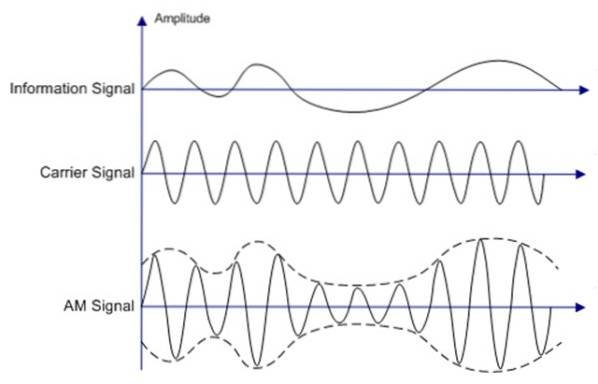
It is noted that the information travels contained in the form that surrounds the AM signal, which is called enveloping.
Using this technique, a signal can be transmitted over long distances, hence this type of modulation is widely used by commercial radio and the civil band, although the procedure can be carried out with any type of signal..
To obtain the information, a receiver is needed, in which a process called demodulation via an envelope detector.
The envelope detector is none other than a very simple circuit, called rectifier. The procedure is simple and inexpensive, but power losses always occur in the transmission process.
Article index
To transmit the message together with the carrier signal, it is not enough to simply add both signals.
It is a non-linear process, in which transmission in the manner described above is achieved by multiply the message signal by the carrier signal, both cosine. And as a result of this Add the carrier signal.
The mathematical form that results from this procedure is a variable signal in time E (t), whose form is:
E (t) = Ec (1 + m.cos 2πfs.t). cos 2πfc.t
Where the amplitude Ec is the amplitude of the carrier and m is the modulation index, given by:
m = Amplitude of the message / Amplitude of the carrier = Es / Ec
In this way: ANDs = m.Ec
The amplitude of the message is small compared to the amplitude of the carrier, therefore:
m <1
Otherwise the envelope of the AM signal would not have the precise shape of the message to be transmitted. The equation for m can be expressed as modulation percentage:
m% = (Es / Ec) x 100%
We know that sinusoidal and cosine signals are characterized by having a certain frequency and wavelength.
When a signal is modulated, its frequency distribution (spectrum) is transferred, which happens to occupy a certain region around the frequency of the carrier signal Fc (which is not altered at all during the modulation process), called bandwidth.
As they are electromagnetic waves, their speed in vacuum is that of light, which is related to wavelength and frequency by:
c = λ.f
In this way, the information to be transmitted from, say, a radio station, travels very quickly to the receivers..
The radio station must transform words and music, all of which are sound signals, into an electrical signal of the same frequency, for example using microphones.
This electrical signal is called auditory frequency signal FA, because it is in the range of 20 to 20,000 Hz, which is the audible spectrum (the frequencies that humans hear).
This signal must be electronically amplified. In the early days of radio it was made with vacuum tubes, which were later replaced by transistors, much more efficient.
The amplified signal is then combined with the signal from radial frequency FR through AM modulator circuits, so that it results in a specific frequency for each radio station. This is the carrier frequency fc mentioned above.
The carrier frequencies of AM radio stations are between 530 Hz and 1600 Hz, but stations that use modulated frequency or FM, have higher frequency carriers: 88-108 MHz.
The next step is to amplify the combined signal again and send it to the antenna so that it can be emitted as a radio wave. In this way it can propagate through space until it reaches the receivers..
A radio receiver has an antenna to pick up the electromagnetic waves coming from the station.
An antenna consists of a conductive material that in turn has free electrons. The electromagnetic field exerts force on these electrons, which immediately vibrate at the same frequency as the waves, producing an electric current..
Another option is that the receiving antenna contains a coil of wire and the electromagnetic field of radio waves induces an electric current in it. In any of the cases, this stream contains the information that comes from all the radio stations that have been captured..
What follows now is that the radio receiver is able to distinguish each radio station, that is, to tune in to the one that is preferred.
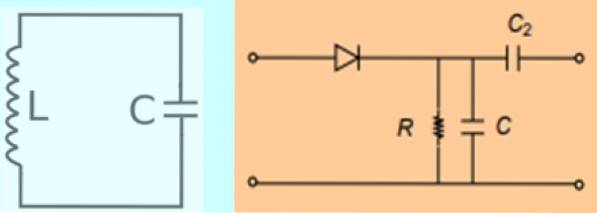
Choosing between the various signals is accomplished by a resonant LC circuit or LC oscillator. This is a very simple circuit that contains a variable inductor L and capacitor C put in series.
To tune the radio station, the values of L and C are adjusted so that the resonant frequency of the circuit matches the frequency of the signal to be tuned, which is none other than the carrier frequency of the radio station: Fc.
Once the station is tuned in, the circuit comes into action demodulator than mentioned at the beginning. He is the one in charge of deciphering, so to speak, the message broadcast by the radio station. It achieves this by separating the carrier signal and the message signal, using a diode, and an RC circuit called low-pass filter.
The already separated signal goes through an amplification process again and from there it goes to the speakers or headphones so that we can hear it.
The process is described here in broad strokes, because in reality there are more stages and it is much more complex. But it gives us a good idea of how amplitude modulation happens and how it reaches the receiver's ears..
A carrier wave has amplitude ANDc = 2 V (RMS) and frequency Fc = 1.5 MHz. It is modulated by a frequency signal fs = 500 Hz and breadth ANDs = 1 V (RMS). What is the equation of the AM signal?
The appropriate values are substituted into the equation for the modulated signal:
E (t) = Ec (1 + m.cos 2πfs.t). cos 2πfc.t
However, it is important to note that the equation includes the peak amplitudes, which in this case are voltages. Therefore it is necessary to pass the RMS voltages to peak multiplying by √2:
ANDc = √2 x 2 V = 2.83 V; ANDs = √2 x 1 V = 1.41 V
m = 1.41 / 2.83 = 0.5
E (t) = 2.83 [(1 + 0.5cos (2π.500.t)] cos (2π.1.5 x 106.t) = 2.83 [(1 + 0.5cos (3.14 x 103.t)] cos (9.42 x 106.t)


Yet No Comments