
A energy diagram is an energy graph that illustrates the process that occurs throughout a reaction. Energetic diagrams can also be defined as the visualization of an electron configuration in orbitals; each representation is an electron from an orbital with an arrow.
For example, in an energy diagram the arrows pointing upwards represent an electron with a positive spin. In turn, the arrows pointing down are responsible for representing an electron with negative spin.
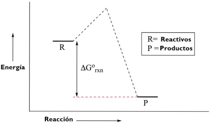
There are two types of energy diagrams. The diagrams of thermodynamics or organic chemistry, which show the amount of energy generated or expended throughout a reaction; starting from the elements being reactive, going through a transition state, to the products.
And inorganic chemistry diagrams, which serve to demonstrate molecular orbitals according to the energy level of the atoms.
Thermodynamic diagrams are diagrams used to represent the thermodynamic states of a matter (typically fluids) and the consequences of handling this material.
For example, an entropic temperature diagram can be used to demonstrate the behavior of a fluid as it changes through a compressor..
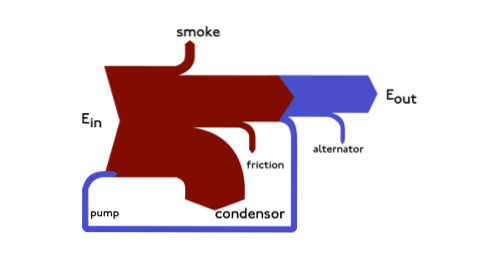
Sankey diagrams are energy diagrams in which the thickness of the arrows are shown proportionally to the amount of flow. An example can be illustrated as follows:
This diagram represents the entire primary flow of energy in a factory. The thickness of the belts is directly proportional to the energy of production, use and losses.
The primary sources of energy are gas, electricity and coal / oil and represent the energy input on the left side of the diagram..
You can also view energy expenses, material flow at a regional or national level, and the breakdown of the cost of an item or services..
These diagrams place a visual emphasis on large energy transfers or flows within a system..
And they are very useful in locating dominant contributions in a general flow. These diagrams often show conserved quantities within the limits of a defined system..
It is used to describe changes corresponding to the volume and pressure measurements in the system. They are commonly used in thermodynamics, cardiovascular physiology, and respiratory physiology..
P-V diagrams were originally called indicator diagrams. They were developed in the 18th century as tools to understand the efficiency of steam engines..
A P-V diagram shows the change in pressure P with respect to the volume of V of some process or processes.
In thermodynamics, these processes form a cycle, so that when the cycle is completed there is no change in the state of the system; as for example in an apparatus that returns to its initial pressure and volume.
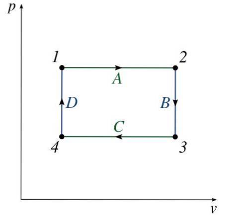
The figure shows the characteristics of a typical P-V diagram. A series of numbered states (from 1 to 4) can be observed.
The path between each state consists of some process (A to D) that alters the pressure or volume of the system (OR both).
It is used in thermodynamics to visualize changes in temperature and specific entropy during a thermodynamic process or cycle..
It is very useful and a very common tool in the area, particularly as it helps to visualize heat transfer during a process..
For reversible or ideal processes, the area under the T-S curve of a process is the heat transferred to the system during that process..
An isentropic process is graphed as a vertical line on a T-S diagram, while an isothermal process is graphed as a horizontal line..
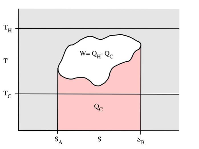
This example shows a thermodynamic cycle that takes place at a hot tank temperature Tc, and a cold tank temperature Tc. In a reversible process, the red area Qc is the amount of energy exchanged between the system and the cold reservoir.
The blank area W is the amount of energy work exchanged between the system and its surroundings. The amount of heat Qh exchanged between the hot tank is the sum of the two.
If the cycle moves to the right it means that it is a heat engine that releases work. If the cycle moves in the opposite direction, it is a heat pump that receives work and moves the heat Qh from the cold tank to the hot tank.
They serve to represent or schematize the molecular orbitals related to atoms and their energy level.
The different conformations of ethane will not have the same energy since they have a different electronic repulsion between hydrogens.
As the molecule is rotated, starting from an already alternating conformation, the distance between the hydrogen atoms of the particular methyl groups begins to decrease. The potential energy of that system will increase until it reaches an eclipsed conformation.
The different types of energy between the various conformations can be graphically represented. In the ethane diagram it is observed how the eclipsed conformations are the maximum energy; on the other hand the alternates would be the minimum.
In this potential energy diagram, ethane starts from an eclipsed conformation. Then they are making turns from 60 ° to 60 ° until the 360 ° are covered.
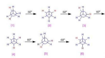
The different conformations can be classified according to energy. For example, alternates 1,3 and 5 have the same energy (0). On the other hand, conformations 2,4 and 6 will have more energy as a consequence of the hydrogen-hydrogen eclipse


Yet No Comments