The superposition theorem, In electrical circuits, it establishes that the voltage between two points, or the current through them, is the algebraic sum of the voltages (or currents if it is the case), due to each source, as if each one acted in a different way. Independent.
This theorem allows us to analyze linear circuits that contain more than one independent source, since it is only necessary to calculate the contribution of each one separately..
Linear dependence is decisive for the theorem to apply. A linear circuit is one whose response is directly proportional to the input.
For example, Ohm's law applied to an electrical resistance states that V = i.R, where V is the voltage, R is the resistance e i is the current. It is then a linear dependence of voltage and current in a resistance.
In linear circuits, the superposition principle is applied taking into account the following:
-Each independent voltage source must be considered separately and for this it is necessary to turn off all the others. It is enough to put to 0 V all those that are not under analysis or to replace them in the scheme with a short circuit.
-If the source is current then you have to open the circuit.
-When considering the internal resistance of both current and voltage sources, they must remain in place, forming part of the rest of the circuit..
-If there are dependent sources, they must remain as they appear in the circuit.
Article index
The superposition theorem is used to obtain simpler and easier to handle circuits. But it should always be borne in mind that it only applies to those with linear responses, as said at the beginning.
So it cannot be used directly to calculate power for example, since power is related to current by:
P = itwo R
Since the current is squared, the response is not linear. It is also not applicable to magnetic circuits involving transformers..
On the other hand, the superposition theorem offers the opportunity to know the effect that each source has on the circuit. And of course, through its application it is possible to solve it completely, that is, to know currents and voltages through each resistance.
The superposition theorem can also be used in conjunction with other circuit theorems, for example Thévenin's, to solve more complex configurations.
In alternating current circuits the theorem is also useful. In this case, we work with impedances instead of resistors, as long as the total response of each frequency can be calculated independently..
Finally, in electronic systems the theorem is applicable for both direct current and alternating current analysis, separately.
-Deactivate all independent sources following the instructions given at the beginning, except the one to be analyzed.
-Determine the output, either voltage or current, that that single source produces.
-Repeat the two steps described for all other sources.
-Calculate the algebraic sum of all the contributions found in the previous steps.
The worked examples below clarify the use of the theorem in some simple circuits.
In the circuit shown in the following figure, find the current through each resistor using the superposition theorem.
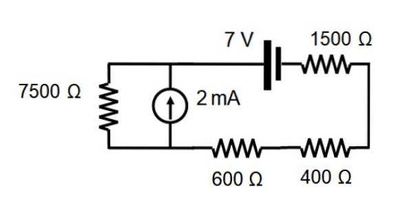
To begin with, the current source is eliminated, which makes the circuit look like this:

The equivalent resistance is found by adding the value of each resistance, since they are all in series:
7500 +600 +400 + 1500 Ω = 10,000 Ω
Applying Ohm's Law V = I.R and clearing the current:
I = V / R = 7 / 10,000 A = 0.0007 A = 0.7 mA
This current is the same for all resistors.
The voltage source is immediately eliminated, to work only with the current source. The resulting circuit is shown below:
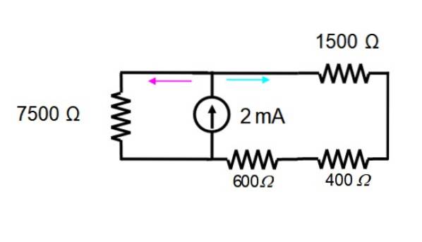
The resistors in the screen on the right are in series and can be replaced by a single one:
600 +400 + 1500 Ω = 2500 Ω
The resulting circuit looks like this:
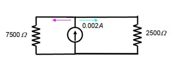
The current of 2 mA = 0.002 A is divided between the two resistors in the figure, therefore the equation of the current divider is valid:
Ix = (Req/ Rx) IT
Where Ix is the current in the resistor Rx, Req symbolizes the equivalent resistance e IT is the total current. It is necessary to find the equivalent resistance between both, knowing that:
1 / Req = (1 / R1) + (1 / Rtwo)
Therefore:
1 / Req = (1/7500) + (1/2500) = 1/1875 → Req = 1875 Ω
For this other circuit, the current through the 7500 Ω resistor is found by substituting values into the current divider equation:
I7500 Ω = (1875/7500). 0.002 A = 0.0005 A = 0.5 mA
While the one that passes through the 2500 Ω resistor is:
I2500 Ω = 2 mA - 0.5 mA = 1.5 mA
Now the superposition theorem is applied for each resistance, starting with the 400 Ω:
I400 Ω = 1.5 mA - 0.7 mA = 0.8 mA
Important: for this resistance, the currents are subtracted, as they circulate in the opposite direction, according to a careful observation of the figures, in which the directions of the currents have different colors.
This same current goes through the 1500 Ω and 600 Ω resistors equally, since they are all in series.
The theorem is then applied to find the current through the 7500 Ω resistor:
I7500 Ω = 0.7 mA + 0.5 mA = 1.2 mA
Important: in the case of the 7500 Ω resistor, note that the currents add up, because in both circuits they circulate in the same direction when passing through this resistance. Again it is necessary to carefully observe the directions of the currents.
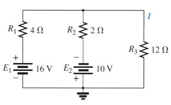
Finding the current and voltage across the 12 Ω resistor using the superposition theorem.
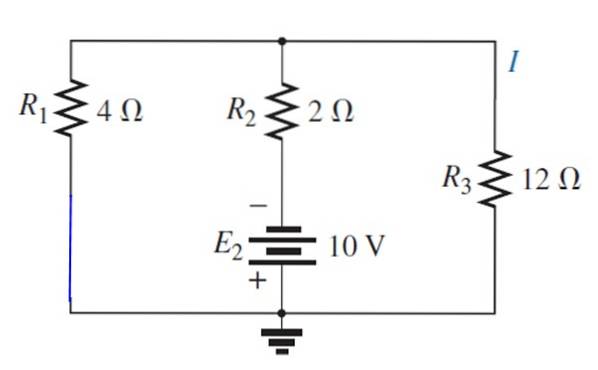
Font E is replaced1 with a short circuit:
The resulting circuit is drawn as follows, to easily visualize the resistances that remain in parallel:
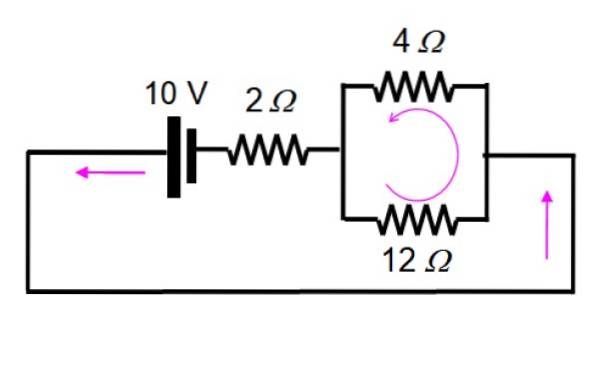
And now it is solved by applying series and parallel:
1 / Req = (1/12) + (1/4) = 1/3 → Req = 3 Ω
This resistance in turn is in series with that of 2 Ω, therefore the total resistance is 5 Ω. The total current is:
I = V / R = 10 V / 5 Ω = 2 A
This stream is divided as:
I12Ω = (3/12) 2 A = 0.5 A
Therefore the voltage is:
V12Ω = 0.5 A × 12 Ω = 6 V
Now source E is activated1:
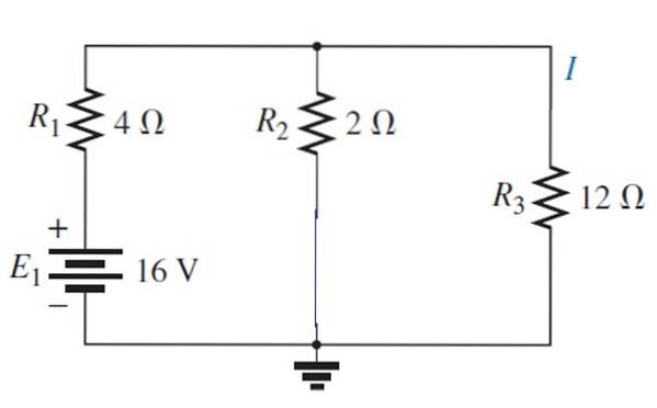
The resulting circuit can be drawn like this:

1 / Req = (1/12) + (1/2) = 7/12 → Req = 12/7 Ω
And in series with that of 4 Ω an equivalent resistance results 40/7 Ω. In this case the total current is:
I = V / R = 16 V / (40/7) Ω = 14/5 A
The voltage divider is applied again with these values:
I12Ω = ((12/7) / 12) (14/5) A = 0.4 A
The resulting current is: 0.5 - 0.4 A = 0.1 A. Note that they have been subtracted, since the current from each source has a different sense, as can be seen in the original circuit.
The voltage across the resistor is:
V12Ω = 0.4 A × 12 Ω = 4.8 V
Finally, the total voltage is: 6V-4.8V = 1.2V


Yet No Comments