The Geometric Tolerances refer to a system of symbols in the drawing of a mechanical part, which serve to express the nominal dimensions and the tolerances allowed thereof.
This system, whose acronym in English is GD&T (Geometric Dimensioning and Tolerance), allows to communicate design information to manufacturers and assemblers that must be followed in order to ensure the correct functionality of the final product..
Geometric and dimensioning tolerances can be defined as an illustrated design language and a functional production and inspection technique. Helps manufacturers with the goal of meeting demands on sophisticated designs consistently, comprehensively, and clearly.
The geometric tolerance system uses standardized symbols to describe them, which are understandable to manufacturers and assemblers..
Article index
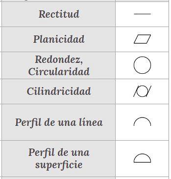
The following symbols are used on individual elements to determine the geometric characteristics of their shape and their metric tolerance:
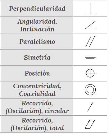
The following are the symbols that are applied to elements or associated parts and that indicate their relative orientation, their position, and their oscillation or travel:
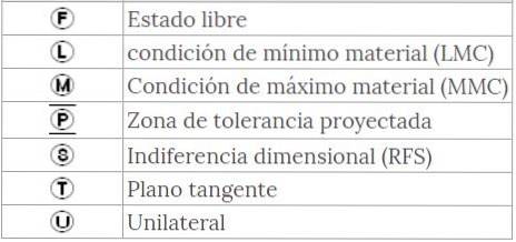
The following set of symbols are modifiers:
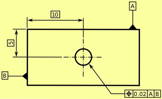
A reference datum, or simply datum, is the theoretically ideal elements that are used as a reference for measurements or tolerances. Generally, a datum is a plane, a cylinder, some lines or a point that is identified, in the drawing or on the plane, with a label that has a letter enclosed in a square and anchored to the surface or reference line..
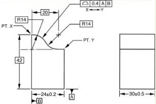
In figure 1 you can see the datum marked with the letter A that is anchored to the upper surface (upper right part) and also the datum B anchored to the left lateral surface of the rectangular piece shown in figure 1.
Note in figure 1 that the distances that define the position of the center of the circular hole on the rectangular part are precisely measured from datums A and B.
Note in the same figure 1 in the lower right part a box that indicates the position tolerance of the center of the hole, also indicating the datums (or reference surfaces) with respect to which said position tolerance is considered. These boxes control the tolerance of the measures, which is why they are called control frames..
Below is a map based on ASME Y14.5 - 2009 standards.
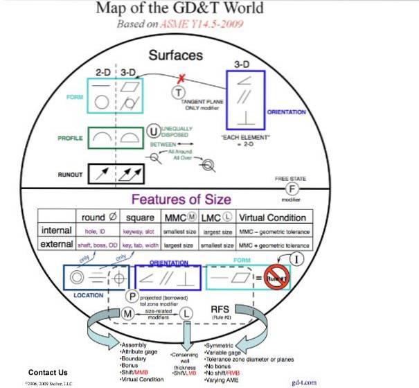
In the upper box (light blue) referring to the shape, there is 2D circularity that is defined as the condition in which all the points that comprise a linear element are circular.
The control defines a tolerance zone consisting of two coaxial circles, radially separated by the distance indicated on the feature control frame. It must be applied to a single cross section line element and not related to a datum.
The following figure shows an example of circularity tolerance and how the dimensioning and geometric tolerance standards are used to indicate them:

The tolerance zone for the outline of a line is a 2D zone (an area) that extends along the entire length of the controlled line element. It may or may not be related to a reference frame of reference.
Cylindricity is defined as the condition in which all the points that comprise a surface are cylindrical. The control defines a tolerance zone consisting of two coaxial cylinders, radially separated by the distance indicated on the feature control frame. It must be applied to an individual surface and not related to a data.
The tolerance zone for the profile of a surface is a three-dimensional zone (a volume) that extends along the entire shape of the controlled surface. It may or may not be related to a frame of reference. Below is a diagram to clarify the point raised:
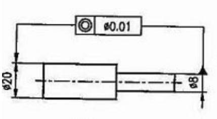
The following example shows a drawing of a part consisting of two concentric cylinders. The figure indicates the diameters of both cylinders, in addition to the datum or reference surface with respect to which the eccentricity tolerance of one cylinder with respect to the other is measured:
The following example shows the cut of a cylindrical part, in which its geometric parallelism tolerances are indicated in two different cases.
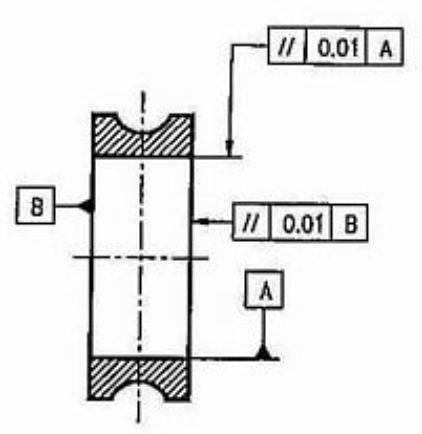
One is the surface or inner cylindrical and its tolerance of parallelism of a generatrix line with respect to the diametrically opposite generatrix line (in this case indicated as datum A), which is indicated in the upper right frame box as: //, 0.01, A.
This is interpreted as that the separation difference between two generatrices should not exceed from one extreme to the other 0.01 (m.m.), this being a tolerance of axial parallelism.
The other case of parallelism tolerance shown in the figure of example 2 is that of the right lateral plane of the part with respect to the left lateral plane that is taken and indicated as the reference surface or datum B. This tolerance of parallels is indicated in the right center frame as: //, 0.01, B.
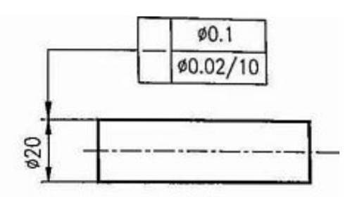
The following figure shows how the straightness tolerance of a cylindrical shaft is indicated. In this case, the nominal diameter of the cylinder is shown, as well as the absolute maximum tolerance in the diameter measurement, as well as the maximum variation allowed for every 10 units of axial travel (parallel to the axis) in the diameter measurement..
The figure in the following example shows how the flatness tolerance of a part is indicated. It is a cylindrical part with a notched flat chamfer showing its flatness tolerance..
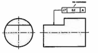
Although it is not indicated in the figure, the datum or reference plane A is the lower cylindrical generatrix line of the part, which theoretically is perfectly flat. Well, the piece of the upper plane has a tolerance to buckling or convexity of 0.2 with respect to the lower generatrix line of reference..


Yet No Comments