The factorial rig It is a simple machine that consists of an arrangement of pulleys with a multiplying effect of the force. In this way, a load can be lifted by applying just the equivalent of a fraction of the weight to the free end of the rope..
It consists of two sets of pulleys: one that is fixed to a support and another that exerts the resulting force on the load. The pulleys are mounted on a generally metallic frame that holds them.
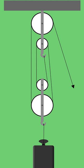
Figure 1 shows a factorial rig consisting of two groups of two pulleys each. This type of pulley arrangement is also called serial rigging or hoists.
Article index
To understand why this arrangement multiplies the force exerted, we will start with the simplest case, which consists of a fixed pulley and a mobile pulley..

In figure 2 we have a pulley A fixed to the ceiling by means of a support. Pulley A can rotate freely around its axis. We also have a pulley B that has a bracket attached to the pulley shaft, on which the load is placed. Pulley B, in addition to being able to rotate freely around its axis, has the possibility of moving vertically.
Suppose we are in an equilibrium situation. Consider the forces acting on pulley B. The axis of pulley B supports a total weight P that is directed downward. If this were the only force on pulley B then it would fall, but we know that the rope that passes through this pulley also exerts two forces, which are T1 and T2 that are directed upwards..
For there to be translational equilibrium, the two upward forces must be equal to the weight supported by the axis of pulley B.
T1 + T2 = P
But since pulley B is also in rotational equilibrium, then T1 = T2. The forces T1 and T2 come from the tension applied to the string, called T.
Therefore T1 = T2 = T. Substituting in the previous equation it remains:
T + T = P
2T = P
Which indicates that the tension applied to the rope is only half the weight:
T = P / 2
For example, if the load were 100 kg, it would be enough to apply a force of 50 kg at the free end of the rope to raise the load at a constant speed..
Let us now consider the stresses and forces acting on an assembly consisting of two arrangements of supports A and B with two pulleys each..

Support B has the possibility of moving vertically, and the forces acting on it are:
- The weight P of the load, pointing vertically down.
- Two stresses on the large pulley and two stresses on the small pulley. In total, four tensions, all of them pointing upwards.
For there to be translational equilibrium it is necessary that the forces pointing vertically up equal in value to the load pointing downwards. That is, it must be fulfilled:
T + T + T + T = P
That is, 4 T = P
From which it follows that the applied force T at the free end of the rope is only a quarter of the weight due to the load that wants to be lifted., T = P / 4.
With this value for the voltage T, the load can be kept static or rise with constant speed. If a voltage greater than this value were applied then the load would accelerate upwards, a condition that is necessary to bring it out of rest..
According to what has been seen in the previous cases, for each pulley of the mobile assembly there is a pair of upward forces exerted by the rope that passes through the pulley. But this force cannot be anything other than the tension applied to the rope at the free end.
So that for each pulley of the mobile assembly there will be an upward vertical force that is equal to 2T. But since there are n pulleys in the moving assembly, it follows that the total force pointing vertically upwards is:
2 n T
For there to be vertical balance it is necessary that:
2 n T = P
therefore the force applied at the free end is:
T = P / (2 n)
In this case it can be said that the exerted force T is multiplied 2 n times on the load.
For example, if we had a factorial rig with 3 fixed and 3 mobile pulleys, the number n would be equal to 3. On the other hand, if the load were P = 120 kg, then the force applied at the free end would be T = 120 kg / (2 * 3) = 20 kg.
Consider a factorial rig made up of two fixed pulleys and two movable pulleys. The maximum tension that the rope can withstand is 60 kg. Determine what is the maximum load that can be placed.
When the load is at rest or moving with constant speed, its weight P is related to the tension T applied to the rope by means of the following relation:
P = 2 n T
Since it is a rig with two mobile and two fixed pulleys, then n = 2.
The maximum load that can be placed is obtained when T has the maximum possible value, which in this case is 60 kg.
Maximum load = 2 * 2 * 60kg = 240kg
Find the relationship between the tension of the rope and the weight of the load, in a two-pulley factorial rig in which the load is accelerated with acceleration at.
The difference of this example with respect to what has been seen so far is that the dynamics of the system must be considered. So we propose Newton's second law to find the requested relation.

In figure 4 we draw in yellow the forces due to the tension T of the rope. The moving part of the rigging has a total mass M. We take as a reference system one at the level of the first fixed pulley and positive downwards.
Y1 is the lowest pulley shaft position.
We apply Newton's second law to determine the acceleration a1 of the moving part of the rig:
-4 T + Mg = M a1
Since the weight of the load is P = Mg, where g is the acceleration of gravity, the above relationship can be written:
-4T + P = P (a1 / g)
If we wanted to determine the tension applied to the rope when a certain weight load P is accelerated with acceleration a1, then the previous relationship would look like this:
T = P (1 - a1 / g) / 4
Note that if the system were at rest or moving with constant speed, then a1 = 0, and we would recover the same expression that we obtained in case 2.
In this example, the same rigging from exercise 1 is used, with the same rope that supports a maximum of 60 kg of tension. A certain load is raised, accelerating it from rest to 1 m / s in 0.5 s, using the maximum tension of the rope. Find the maximum weight of the load.
We will use the expressions obtained in exercise 2 and the reference system of figure 4 in which the positive direction is vertical down.
The acceleration of the load is a1 = (-1 m / s - 0 m / s) / 0.5 s = -2 m / s ^ 2.
The weight of the load in kilogram-force is given by
P = 4 T / (1 - a1 / g)
P = 4 * 60 kg / (1 + 2 / 9.8) = 199.3 kg
This is the maximum possible weight of the load without the rope breaking. Note that the value obtained is less than that obtained in example 1, in which the load was assumed to have zero acceleration, that is, at rest or with constant velocity..


Yet No Comments